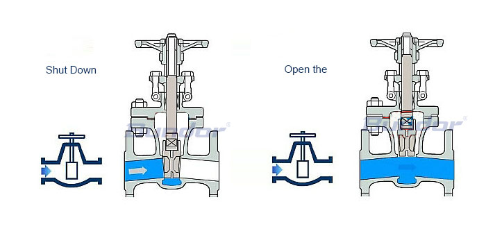
Gate valve structure diagram gate valve working principle
A gate structure
Gate valve are valves in which the gate shutoff member moves vertically along the center line of the path.Generally by the body, seat, stem, gate, cover, sealing ring several parts, can be converted to a variety of electric gate valve pneumatic gate valve through the transmission device and gate valve equipped, in the pipeline can only be fully open and fully shut off with, can not be adjusted and throttling.
How gate valves work
Gate valve gate along with the stem for linear movement, usually in the lifting rod has a trapezoidal thread, through the nut at the top of the valve and the guide groove on the valve body, the rotation movement into linear movement, that is, the operation torque into operation thrust.
When gate valve is closed
The sealing surface can be sealed only by the medium pressure, that is, the sealing surface of the gate can be pressed to the other side of the seat to ensure the sealing surface by the medium pressure, which is self-sealing.Most gate valves are used for forced sealing, that is, when the valve is closed, to rely on external force to force the gate to the seat, in order to ensure the sealing surface of the seal.
When gate valve is open
When the gate elevation is equal to 1:1 of the valve size, the flow path is completely clear, but this position cannot be monitored during operation.The actual use of the stem is marked by the apex of the valve, that is, the open position, as its full open position.In order to consider the temperature change of the lock phenomenon, usually open to the vertex position, and then rewind 1/2-1 turn, as the position of the fully open valve.Therefore, the fully open position of the valve is determined by the position of the gate (i.e., travel >).
 简体中文
简体中文 Русский
 Español
 Bundor - Butterfly, Gate, Check, Ball, Globe Valve Manufacturer, Supplier & Distributor
